
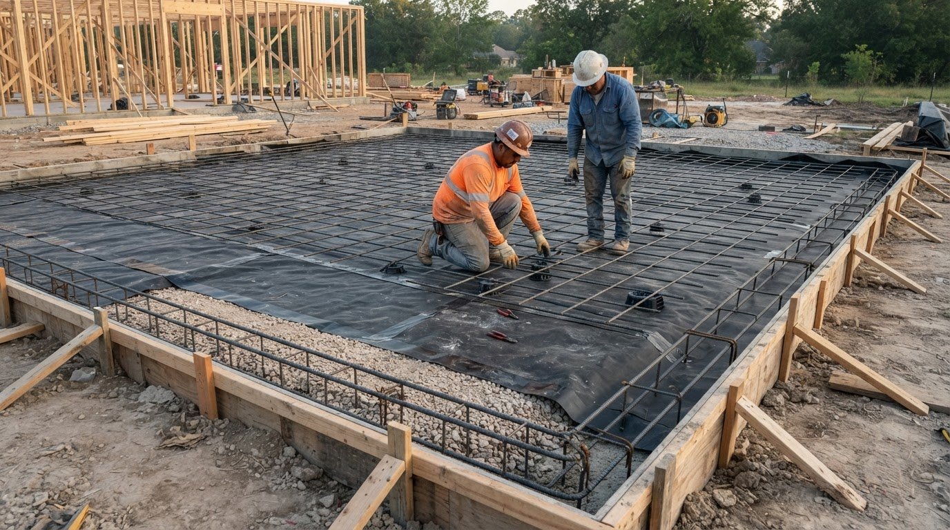
The essential reinforced slab on grade details begin with the foundation itself: a slab-on-grade is a concrete slab that bears directly on prepared ground. A typical residential slab is 4-6 inches thick, but its footing, reinforcement, and supporting layers depend on the building and the loads it must carry.
Slab thickness matters, but it is only one part of a sound foundation. The aggregate base, footing, vapor barrier, and reinforcement position all affect how the assembly performs. A pre-pour inspection helps confirm that the planned layers are in place before concrete placement.
This overview explains how the components work together, what affects slab thickness and reinforcement, and what construction teams examine before the pour. You’ll get a clearer picture of the construction sequence and the details that support a durable slab-on-grade foundation.
Key Takeaways
- Understand what makes a slab-on-grade foundation and why slab thickness depends on its intended use.
- See how perimeter footings and compacted aggregate support the slab as a complete foundation system.
- Learn how the vapor barrier and reinforcement fit within the construction layers, and why reinforcement position matters.
- Know which load conditions can change slab thickness and reinforcement requirements.
- Understand what a pre-pour inspection checks before concrete placement begins.
What does slab-on-grade mean?
A slab-on-grade is a concrete floor placed over prepared ground, rather than suspended above a basement or crawlspace. The ground and supporting base carry the slab, while perimeter footings may support the building’s walls. Reinforced slab on grade details include the supporting layers, slab thickness, reinforcement, joints, and intended loads.
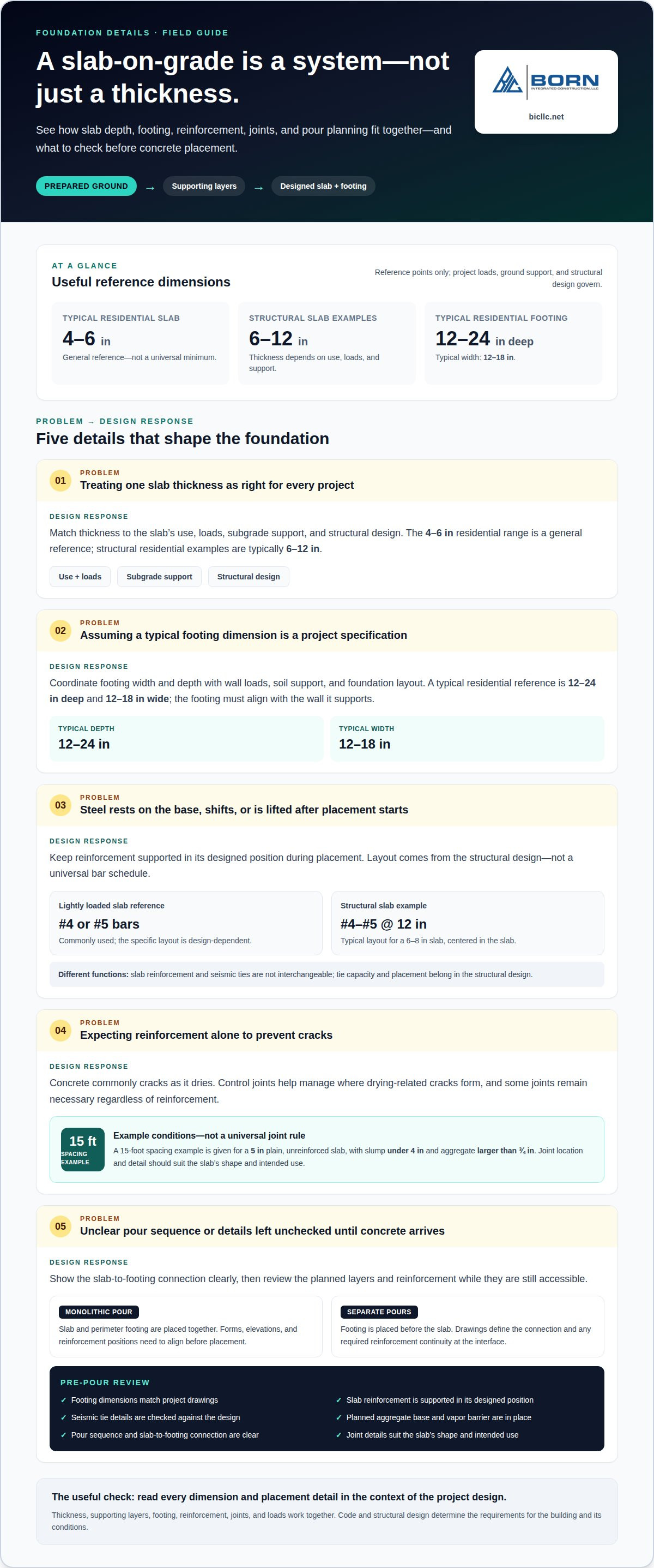
For typical residential construction, slab thickness is commonly 4-6 inches. That range is a general reference, not a universal minimum for every building. Structural slabs-on-grade may be thicker; residential structural examples typically measure 6-12 inches. The required depth depends on the slab’s use, loads, subgrade support, and structural design.
Welded wire fabric and reinforcing bars both add steel to concrete, but their layouts differ. Wire fabric forms a mesh, while deformed bars are arranged in specified directions and spacing. Typical lightly loaded slabs commonly use #4 or #5 bars; one example uses a single layer of #6 bars at 7½ inches on center. Steel must remain at its designed position during placement.
U.S. building codes and ACI standards do not set one reinforcement layout for every slab-on-grade. The applicable code and structural design determine requirements for the building’s use and loads. Basic flatwork generally does not require structural reinforcement, while structural slabs need details suited to their design conditions.
Control joints help manage where drying-related cracks form, and some joints remain necessary regardless of reinforcement. One example recommends 15-foot spacing for a 5-inch plain, unreinforced slab with slump under 4 inches and aggregate larger than ¾ inch. Joint location and detail should also suit the slab’s shape and intended use.
Common reinforcement problems include steel resting on the base, shifting during placement, or mesh being pulled upward after concrete placement begins. These issues can leave reinforcement outside its intended position. Concrete commonly cracks as it dries, and misplaced steel or poorly planned joints can undermine crack-control intent. A pre-pour review addresses these details while they are still accessible.
California’s 2020 Standard for Residential Construction in High Wind Regions states that concrete slab-on-grade must be at least 31/2 inches thick. California’s 2014 Standard for Residential Construction in High Wind Regions states that concrete slab-on-grade must be at least 3 1/2 inches thick. These are minimums specified in the two named standards; they should not be treated as a universal thickness rule for every slab-on-grade project. The standard’s title and scope matter when determining whether its stated minimum applies to a particular building.
Minimum thickness is one part of a slab design, not a complete description. It does not specify the supporting layers, reinforcement, joints, or loads, which must also be addressed in the project design. The two California standards provide a specific example of a stated minimum for residential construction in high-wind regions. When reviewing a proposed slab, distinguish that requirement from the broader design decisions that affect performance. Read the stated thickness alongside the project requirements, rather than assuming that meeting a minimum resolves every design question.
Perimeter footing dimensions and reinforcement
A perimeter footing supports exterior walls and transfers their loads into the ground. Its dimensions and connection to the slab affect how the foundation carries loads around the building. The detail must coordinate the footing, wall, and slab edge as parts of one structural assembly.
Perimeter Footing Dimensions
A typical residential perimeter footing is 12 to 24 inches deep and 12 to 18 inches wide. These dimensions are reference points, not a universal design for every site or structure. Wall loads, soil support, and foundation layout influence the required geometry. The footing’s position also needs to align with the wall it supports, so the drawings coordinate its width and depth with the slab edge.
Reinforcement follows the structural design rather than a default bar size or spacing. A typical layout for a 6-8-inch structural slab-on-grade is #4-#5 bars at 12 inches on center, centered in the slab. That describes slab reinforcement, not an automatic footing schedule. Footing steel may differ because its depth, width, and role in supporting wall loads differ from the slab’s.
Seismic ties connect foundation elements and address tension or compression forces at the connection. Their capacity and placement belong in the structural design for the slab-on-grade foundation. They should not be inferred from the slab’s bar layout alone: a slab mat and a footing tie serve different functions. Construction details need to show how the tie connects the relevant foundation components.
Monolithic and Separate Pours
A monolithic pour places the slab and perimeter footing concrete together, while a separate pour constructs the footing before the slab. The main difference is the placement sequence and the interface between the concrete placements. The choice affects how drawings show the connection and how crews coordinate forming, reinforcement, and placement.
With separate pours, the footing is placed before the slab concrete meets or overlays it. Drawings need to define the connection and any required reinforcement continuity across the interface. With a monolithic pour, footing and slab forms, elevations, and reinforcement positions must align before placement. Either sequence needs a clear detail that matches the structural design.
Before placement, the construction team compares footing dimensions, slab reinforcement, and seismic tie details with the project drawings. The review also confirms that reinforcement is supported in its designed position. Resolving discrepancies before the pour keeps the connection accessible and helps ensure the built footing and slab match the intended foundation detail.
Aggregate base course
The aggregate base course is the compacted stone layer between prepared ground and the concrete slab. It provides a more uniform support surface and helps distribute slab loads across the ground. A typical slab-on-grade base course is 4-6 inches of compacted aggregate. That thickness is a general reference; project requirements can vary with the floor’s use and the loads it supports.
Compaction is central to base performance. Loose or uneven aggregate can leave areas without consistent support beneath the concrete. Those differences can contribute to slab movement or cracking under load. The construction team prepares the base to the specified elevation and compaction requirements, giving the slab consistent support across its footprint.
Project use can set a specific minimum thickness. Pennsylvania NRCS floors under liquids require a minimum stone subbase thickness of 4 inches. Pennsylvania NRCS stacking floors with single axle loads of 15,000-20,000 pounds also require at least 4 inches. For floors supporting stationary liquid storage tanks, the minimum subbase thickness is 6 inches. These examples show why one typical base dimension cannot be applied to every slab.
The aggregate layer also provides a working surface for the next construction activities. Its final elevation affects the space available for the slab and other specified layers. If the base surface varies, concrete thickness may vary too, unless placement accounts for those differences. A level, well-compacted base supports consistent bearing and accurate slab depth.
Material selection and installation should follow the project design. Aggregate gradation, moisture, and underlying soil can affect how well the base compacts and performs. Thickness alone does not describe the full base specification. Construction documents establish the intended material and preparation requirements, while field conditions can affect how crews sequence and manage placement.
Before concrete placement, the base is reviewed as part of the foundation assembly. The construction team checks that its elevation and surface condition align with the design and that later layers can be installed as detailed. For example, a floor designed over a 6-inch subbase must preserve that specified depth beneath the slab. Coordination at this stage helps prevent the base from being obscured before its condition is assessed.
These details matter because a concrete slab relies on support below it, not reinforcement alone. A correctly specified aggregate base, compacted and set to the intended elevation, provides a consistent platform for the layers above. Pennsylvania NRCS examples illustrate the relationship: base thickness varies with floor use and the loads it must support.
Slab-on-grade foundation construction layers
A slab-on-grade assembly follows a sequence: prepared subgrade, aggregate base, specified vapor barrier, supported reinforcement, and concrete. Each layer establishes conditions for the next. Elevation mismatches can affect slab depth, while misplaced reinforcement can leave steel outside its intended position. Construction drawings coordinate these layers as one system, rather than treating the concrete pour as an isolated task.
A vapor barrier helps limit moisture movement through the slab assembly. The described minimum thickness range is 10-15 mil, but the project documents determine the specified material and placement. Seams, penetrations, and edges need coordination so the membrane remains continuous as other work proceeds. If the design includes a polyethylene slip sheet beneath a post-tensioned slab, it can keep the coefficient of friction at or below 0.5.
Reinforcement needs stable support before and during concrete placement. For crack control, reinforcement placement should follow the project design and remain in its intended position within the slab. A cited ACI 360R recommendation places reinforcement 1.5-2 inches from the top surface or at one-third of the slab depth from the top. A typical layout for a 6-8-inch structural slab uses #4-#5 bars at 12 inches on center, centered in the slab.
Welded wire fabric also requires support to maintain its intended elevation. The cited placement guidance calls for at least one chair per 25 square feet of mesh. Prefabricated sheets are recommended over rolls because they help keep the fabric properly located in the concrete. Pulling mesh upward after concrete placement begins is unreliable; workers moving across the slab can push it back down.
Before the pour, the construction team checks the sequence against the drawings, including membrane continuity, reinforcement layout and support, and clearance for concrete placement. This review catches displacement while the layers are accessible. For example, if a bar mat shifts during work, crews can correct its position before concrete covers it. Reinforcement must be held in place, not merely present.
Layer coordination also affects the finished slab’s thickness and reinforcement cover. The specified base elevation, membrane, chair height, and steel location must fit within the planned concrete depth. A 6-8-inch slab with bars centered requires a different support arrangement than reinforcement placed near the upper third. The construction team therefore confirms the whole cross-section before placing concrete, preserving the designed relationship between every layer.
How thick should a reinforced slab on grade be for different loads?
Slab thickness depends on the load, its contact area, and support beneath the concrete. One example describes a 6-inch slab placed on earth carrying about 30,000 pounds on a 6-inch-by-6-inch area. That example is not a universal capacity rating. Concentrated loads, moving equipment, subgrade support, reinforcement, and joint layout all influence the design.
Lightly loaded floors and structural slabs serve different purposes, so a single thickness cannot suit every project. One engineer’s practice for structural slabs-on-grade is a 10-inch slab with two reinforcing mats. A typical layout for a 10-12-inch structural slab is a double mat of #5 bars at 12 inches on center. These examples show how depth and reinforcement work together, not a one-size-fits-all specification.
Load assessment starts with how forces reach the slab. A broad, evenly distributed load differs from a wheel, column, or machine leg concentrating force over a small area. The design considers the load’s location and contact area, and whether it moves across the floor. For example, a forklift route creates a different loading pattern from stationary storage, even if both use the same floor.
Support conditions matter too. Variations in subgrade support can affect how a slab responds to applied loads, so thickness cannot be assessed separately from the prepared ground and base. The design also coordinates reinforcement position and joints with the slab’s dimensions. A thicker section with reinforcement in the wrong position does not match the intended structural detail.
Project teams should distinguish design examples from approved project criteria. Drawings need to reflect actual use, anticipated equipment, concentrated loads, and support conditions. If equipment specifications change after slab design, the load assumptions may change too. That can affect thickness, reinforcement, and joint details, making early coordination between the project team and construction professionals important.
For a useful review, organize the information around the loads the floor will carry, where those loads act, and whether equipment travels over the slab. Those factors provide a practical basis for evaluating the design instead of selecting thickness from a generic example. A 6-inch example or 10-inch practice should be understood in context, not treated as a direct recommendation for another project.
To discuss how project loads inform slab planning, plan your foundation requirements.
Born Integrated Construction: Slab on Grade
Born Integrated Construction provides Slab on Grade construction for projects requiring a coordinated concrete foundation. The work brings the design’s footing, aggregate base, reinforcement, and concrete placement together as one assembly. The company is a natural next step when a project moves from understanding slab details to planning construction.
Early coordination helps align project requirements with the planned foundation system. Load conditions, slab dimensions, and construction layers inform the design and work sequence. Born Integrated Construction also provides Concrete Paving, Podium Slabs, and CIP Garages for different concrete construction needs.
For a slab-on-grade project, contact Born Integrated Construction to discuss the construction scope and project requirements.
Carry the design into construction
The next step is to translate the project’s design intent into a coordinated construction scope. A project-specific review of reinforced slab on grade details can align structural requirements, site conditions, and construction sequencing before work proceeds. Clear project information, including intended use, load expectations, drawings, and schedule priorities, gives the construction team a practical basis for planning.
Born Integrated Construction offers Slab on Grade, Concrete Paving, and Podium Slabs. These services address different concrete project needs, with the appropriate scope shaped by the project design and requirements. Early coordination helps establish how the work will proceed and which construction interfaces need attention.
For a discussion about your project, contact Born Integrated Construction. A well-defined scope is a solid starting point for moving the work forward with confidence.
Frequently Asked Questions
What are the standard details for a reinforced concrete slab on grade?
There isn’t one standard detail for every slab; the drawings define the project-specific assembly. A coordinated detail set identifies slab sections, reinforcement placement, joint locations, edge transitions, and penetrations through the concrete. The practical check is consistency: section drawings, structural notes, and placement plans should describe the same work. For Texas projects in Houston, Austin, San Antonio, Dallas, Fort Worth, San Marcos, New Braunfels, Boerne, Beaumont, Conroe, The Woodlands, and Arlington, project documents guide the site-specific design.
What subgrade preparation and base course are required beneath a reinforced slab on grade?
The subgrade is prepared to provide a stable, even surface for the designed base and slab assembly. Construction documents establish the base material, elevation, and compaction requirements. A useful coordination point is the finished base elevation: it must leave room for the specified membrane, reinforcement supports, and concrete depth. For example, changing the base elevation can affect the slab section if the planned top elevation remains fixed.
How should slab-on-grade edges, thickened edges, and footings be detailed?
Edge details should show how the slab, thickened edge, and perimeter footing relate to the supported wall. They identify concrete geometry, reinforcement locations, and connections between foundation elements. A thickened edge isn’t automatically a substitute for a separate footing; the design must establish its structural role. When the footing and slab are poured separately, drawings should clarify their connection and reinforcement continuity so the interface can be built as intended.
What vapor barrier and insulation details are used beneath a reinforced slab on grade?
A vapor barrier is detailed beneath the slab when the design calls for moisture control, with seams, edges, and penetrations coordinated to maintain continuity. Insulation type, location, and extent depend on the project design and applicable requirements, so there is no single detail for every building. Construction drawings should show how insulation meets the slab edge and foundation, allowing these layers to fit without disrupting the planned concrete section.
What control joint spacing and details are recommended for reinforced slabs on grade?
Some control joints remain necessary even when a slab is reinforced, and their locations should suit the slab’s shape and intended use. The article’s 15-foot spacing example applies to a 5-inch plain, unreinforced slab with slump under 4 inches and aggregate larger than ¾ inch.