
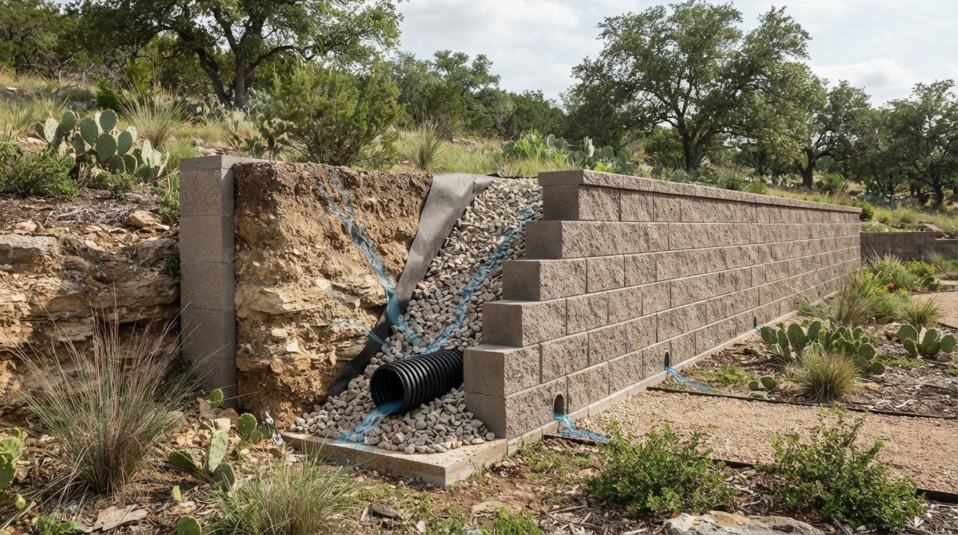
A retaining wall can be built to hold back soil, but trapped water can undermine its stability. Effective retaining wall drainage solutions typically combine at least 12 inches of gravel behind the wall with a footing drain that slopes toward an outlet, allowing groundwater to escape instead of building up pressure.
It’s easy to focus on the visible wall and overlook water moving through the soil behind it. Blocked outlets, poorly placed pipes, or missing weep holes can contribute to pressure, movement, and damage over time. Understanding how drainage works helps identify where a wall may be vulnerable.
This article explains how gravel, filter fabric, perforated pipes, and weep holes manage groundwater, and why placement matters. You’ll also learn how poor drainage can contribute to wall failure and which installation oversights can compromise the system.
Key Takeaways
- Trapped groundwater can build pressure behind a retaining wall and contribute to movement or failure.
- A gravel drainage zone and separator help direct water away while limiting soil migration.
- Perforated pipe collects subsurface water; a sloped outlet gives it a clear route away from the wall.
- Weep hole size and spacing should reflect wall height and drainage demand, and the openings need to remain clear.
- Bulging, cracking, or leaning can signal that a wall’s drainage or structural system needs attention.
What Strategies Are Most Commonly Employed to Curtail Ground Water and Improve Drainage for Retaining Walls?
Groundwater control depends on the soil, water movement, and drainage path behind the wall. Effective retaining wall drainage solutions combine permeable backfill, separation fabric, and a functioning outlet.
Groundwater and Site Conditions
Geotechnical conditions describe the soil and groundwater that influence pressure against a retaining wall. Clay holds water more readily than free-draining granular soil, so the same wall layout can face different drainage demands from site to site.
Groundwater movement, surface runoff, slope, and soil layers affect where water collects. Proper backfill and grading direct water toward drainage instead of allowing it to pool behind the wall. Permit and code requirements vary by jurisdiction; wall height, grading, and groundwater conditions are relevant considerations.
Geotextile and Filter Fabric
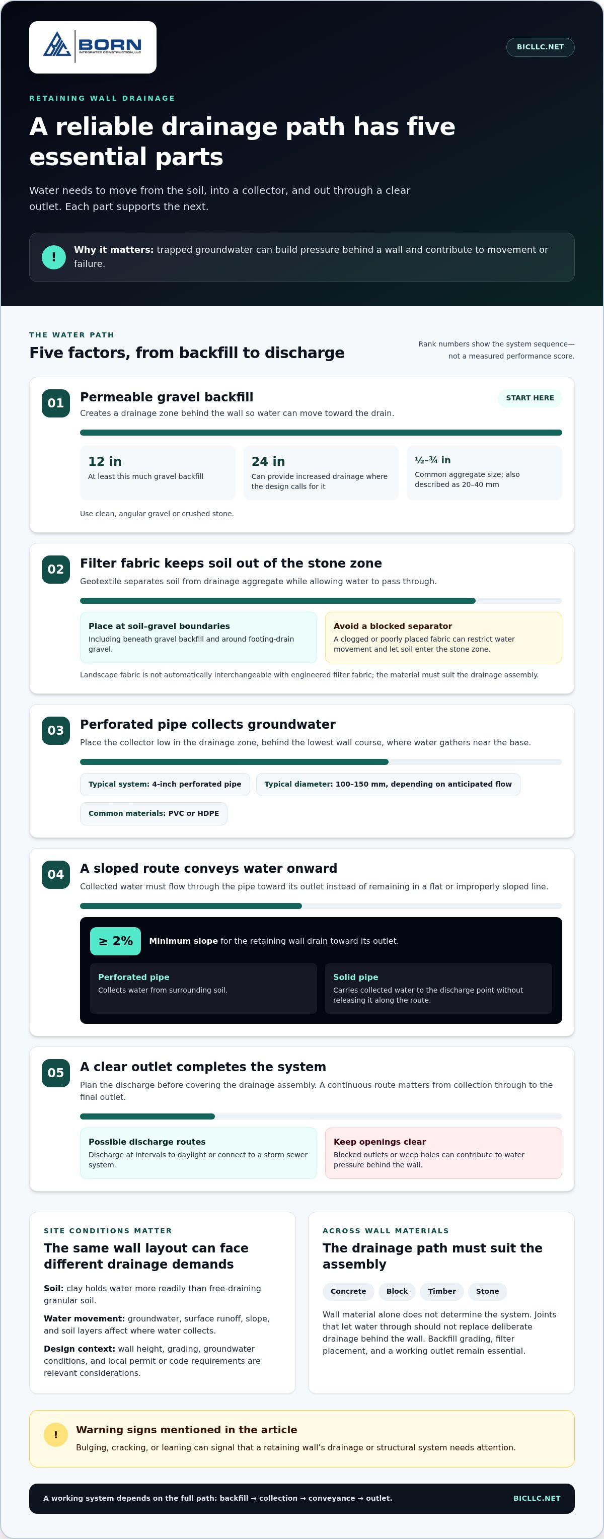
Geotextile filter fabric separates soil from drainage aggregate while allowing water to pass through. Place it wherever soil and gravel meet, including beneath gravel backfill and between footing-drain gravel and surrounding soil.
At weep holes, geotextile can help prevent soil from migrating through the openings. Landscape fabric is not automatically interchangeable with engineered filter fabric; the material must suit the drainage assembly. A clogged or poorly placed separator can restrict water movement and allow soil into the stone zone.
Selecting Gravel, Fabric, and Pipe
Use clean, angular gravel or crushed stone behind the wall. Drainage guidance commonly specifies aggregate between 1/2 and 3/4 inch, also described as 20-40 mm. Provide at least 12 inches of gravel backfill; 24 inches can provide increased drainage where the design calls for it.
A typical system uses a 4-inch perforated drain pipe behind the lowest wall course, surrounded by drainage aggregate. Filter fabric separates that aggregate from soil, while the pipe carries collected water toward an outlet. This combination answers the practical selection question: clean stone, compatible geotextile, and a perforated footing drain with a clear discharge route.
Drainage Across Wall Materials
Drainage principles apply to concrete, block, timber, and stone walls, but the drainage path must suit each assembly. Concrete and block walls may use footing drains and weep holes; timber and stone designs also need a clear route through or around the retained soil.
Wall material alone does not determine the required drainage system. Joints in block or stone, for example, may allow water through, but they should not replace deliberate drainage behind the wall. Backfill grading, filter placement, and a working outlet remain essential for all four materials.
Perforated pipe systems and French drains
A perforated drain collects groundwater from the soil behind a wall. A solid pipe carries that water toward an outlet, keeping collection and discharge as separate functions.
Perforated and Solid Drain Pipes
Perforated pipe has openings that admit subsurface water along its length. Solid pipe has no collection openings, so it conveys water without drawing it from the surrounding soil. Using each pipe for its intended role helps prevent water from remaining trapped behind the wall.
Retaining wall perforated pipes are typically 100-150 mm in diameter, depending on anticipated flow rates. PVC and HDPE are commonly used materials because they resist crushing and chemical degradation. Pipe diameter and material affect how the system handles incoming water and the conditions surrounding the wall.
A perforated line needs a route for collected water to leave the drainage zone. Connect it to solid pipe where water must travel from the wall to a discharge point. This transition matters: perforated pipe collects water, while solid pipe carries it onward without releasing it along the route.
French Drains and Pipe Placement
A French drain is a subsurface route that uses aggregate and perforated pipe to collect and convey groundwater. Behind a retaining wall, the perforated section sits under or behind the wall, where it can intercept water moving through the soil.
Place the pipe low in the drainage zone so water can enter as it gathers near the wall’s base. A retaining wall drain should have a minimum slope of 2% toward its outlet. Without that fall, water can remain in the pipe rather than flow away.
Plan the outlet before covering the drainage assembly. Perforated pipe should discharge at regular intervals to daylight or connect to a storm sewer system. The solid section carries water from the wall to the discharge point, limiting seepage along the route.
For example, a wall beside a slope may receive groundwater moving downhill through the soil. The perforated section collects that flow behind the wall, and the sloped pipe directs it toward an outlet. A clear, continuous path matters from collection to discharge, including where the pipe changes from perforated to solid.
Placement and slope work together. A correctly positioned pipe can still hold water if its route is flat or improperly sloped. A properly sloped line can also miss groundwater if it sits outside the drainage zone. Coordinating the pipe location, slope, and outlet creates a functional route for water to leave the wall assembly.
Weep hole spacing, size, and placement
Weep holes let water escape through a retaining wall. Their position, diameter, spacing, and protection affect how well drainage works.
Weep Hole Placement
Weep holes are openings through a wall that release water from behind it. Their location matters because water collecting low in the backfill needs a direct exit instead of pressing against the wall.
Place openings near the base, where collected water can drain outward. Each hole should incline slightly downward toward the exposed face, helping water flow out rather than remain in the opening. Geotextile filters behind weep holes help prevent soil from migrating through them.
For example, a row of openings near the wall’s lower portion can release water from the drainage zone. If the openings sit above that zone, water may remain below them. The surrounding gravel and filter material should connect to the openings, providing a path from the backfill to the wall face.
Wall height affects how carefully the openings must be planned. Weep holes are especially vital for retaining walls over 4 feet tall. Their placement should work with the wall’s drainage layout, rather than being treated as isolated holes drilled through the face.
Weep Hole Size and Spacing
Weep-hole diameter and spacing determine how many exit points serve the retained soil. For walls smaller than 6 feet, a common recommendation is holes about 1-1/2 inches in diameter, spaced at 8-foot intervals.
For walls around 6 feet or taller, recommended openings are 3 to 4 inches in diameter, spaced every 3 to 4 feet. Larger openings and closer spacing provide more discharge points for walls with greater drainage demand. These dimensions describe guidance, not a universal layout for every wall.
Other general spacing guidance places weep holes 6 to 10 feet apart, depending on wall height, design, and expected drainage load. The difference between that range and closer intervals for taller walls shows why height and water conditions matter. A tall wall beside a slope may need a denser arrangement than a shorter wall in free-draining soil.
Spacing should also align with the drainage material behind the wall. A hole without a clear route through gravel can remain ineffective, even at the recommended diameter. A geotextile filter can limit soil migration while allowing water to reach the openings.
Assess the full pattern, not one opening alone. For example, a wall around 6 feet tall with openings every 3 to 4 feet has more frequent outlets than one using 8-foot intervals. Consistent placement, downward inclination, and clear connections to drainage aggregate support reliable discharge along the wall.
Common block wall drainage mistakes
Maintain a block wall drainage system by checking visible outlets, weep holes, and the wall face for obstructions or movement. If water fails to discharge, inspect the outlet and openings first, then look for soil migration, bulging, or cracking that may indicate a deeper blockage or pressure problem.
One common mistake is providing too little drainage coverage behind the wall. Retaining wall backfill should extend at least 12 inches behind the wall, creating space for drainage material to collect and route water. A narrow gravel zone can leave sections of soil saturated, particularly where surface water runs toward the wall instead of away from it.
Geocomposite drainage panels can fail when joints are poorly overlapped or unsealed. Gaps may let soil enter the drainage core or interrupt the water path. Panel edges need proper overlaps and seals, and the assembly should connect to components such as collector pipes. A panel that ends short of the collection route cannot direct water effectively.
Compaction errors create another problem. Compact soil above the drainage zone in lifts, but don’t heavily compact the drainage gravel itself. Excessive compaction can reduce the open spaces that let water move downward. For example, aggressively compacting both soil and stone can restrict flow toward a footing drain.
Weep holes are especially vital for retaining walls over 4 feet tall, yet blocked or soil-filled openings cannot release water. Inspect each visible opening for sediment, vegetation, or debris. Geotextile filters can help prevent soil from migrating through the holes, while a clear exterior opening allows collected water to discharge.
Check outlets after rainfall for water flow, sediment, or signs of blockage. If water stands behind a wall or exits at unexpected points, trace the route from the backfill to the outlet. A flat or obstructed pipe can hold water, while a damaged connection can interrupt discharge. One clear weep hole does not prove the whole system is working.
Watch the block face for changes as you check drainage. A new bulge, widening crack, or leaning section combined with poor discharge may indicate pressure buildup. Clear surface debris from outlets and keep grading from directing runoff toward the wall. If movement continues or multiple openings remain blocked, the drainage assembly and wall condition need closer assessment.
During a closer review, trace the drainage route as a connected assembly rather than judging each component alone. Check that panel joints overlap and seal properly, and that panels connect with components such as collector pipes. Follow the route from the panel toward collection and discharge points, looking for breaks in continuity, unfinished edges, or connections that do not meet the next component. Compare these observations with what is visible at the outlets and on the wall face. If the route is unclear or discharge remains poor, include the panel connections in the assessment instead of focusing only on the openings.
How poor drainage can cause retaining wall failure
Water trapped behind a retaining wall adds pressure where the structure is designed to resist soil. As water accumulates, saturated backfill can press harder against the wall, contributing to movement, cracking, or loss of stability. Drainage is part of the wall’s structural performance, not an optional finishing detail.
Failure can develop through connected problems. A blocked outlet prevents collected water from escaping, so saturated soil presses against the wall for longer. If the wall starts moving, joints may open or cracks may widen, allowing more water into the assembly. A bulge, leaning face, or new crack near a drainage outlet deserves prompt attention.
Surface grading can add to the problem. Runoff directed toward a wall, for example, can feed water into the backfill faster than the drainage route releases it. Water can also carry fine soil toward openings or drainage components. As material migrates, voids may form behind the wall while clogged pathways reduce discharge. These conditions can compound rather than appear as a single defect.
Wall height and surrounding loads influence the consequences. Retaining walls under 4 feet may qualify as gravity walls with little to no reinforcement, subject to local building codes. Walls 4 to 6 feet high often need moderate reinforcement and layered drainage, particularly where slopes or surcharge loads are present. Walls over 6 feet are considered critical-height structures requiring formal civil or structural engineering design.
Drainage should be included in structural engineering design for walls over 6 feet. Engineering input also matters where a 4-to-6-foot wall retains a slope or surcharge load, or where groundwater creates demanding site conditions. The design must account for wall height, retained soil, nearby loads, water movement, and a dependable discharge route.
Pay attention to changes rather than waiting for visible failure. After rainfall, note whether outlets discharge, water pools behind the wall, or cracks and alignment change. A system that looks clear at the face may still have a blocked pipe or interrupted route behind it. Compare observations over time, especially after wet conditions.
When retaining wall drainage solutions are planned alongside structural requirements, the system can address water movement before pressure becomes a persistent burden. For construction planning, review retaining wall project examples to see how wall construction fits within broader site work.
Born Integrated Construction: Concrete Paving
Born Integrated Construction provides Concrete Paving for projects where durable site surfaces are part of the broader construction scope. When retaining wall work connects with pavement or other concrete elements, coordinated planning helps align grades, transitions, and project requirements.
Born Integrated Construction also provides Slab on Grade, Podium Slabs, and CIP Garages. These services support varied concrete construction needs, from ground-level slabs to elevated structures. Retaining wall drainage still needs to address groundwater, backfill, and outlets directly; Concrete Paving is relevant when adjacent surfaces are part of the project.
Contact Born Integrated Construction to discuss Concrete Paving for your project.
Plan the Next Stage With Confidence
Use a drainage review as a starting point for broader site coordination. Before work begins, note where water travels across the property, record visible wall movement, and identify how nearby construction could affect surface grading. These observations help focus the project discussion on actual conditions rather than assumptions.
For new construction, consider retaining wall drainage solutions alongside the surrounding site and concrete work. Coordinating these elements early can clarify how the wall, adjacent surfaces, and project sequence fit together. For an existing wall, describe the changes you have observed and where water collects or exits. Clear site information supports a more focused discussion about next steps.
Born Integrated Construction’s concrete construction capabilities may suit projects where retaining walls connect with wider site improvements. Share your project requirements with the team to discuss the work involved. Contact Born Integrated Construction to begin a conversation, and move forward with a well-considered plan.
Frequently Asked Questions
How Can Poor Drainage Lead to Retaining Wall Failure?
Poor drainage can allow water to accumulate in retained soil, increasing lateral pressure against the wall. Continued pressure may contribute to movement, loosened joints, or widening cracks. After rainfall, note where water appears and compare the wall’s alignment with earlier observations. A pattern of new seepage alongside progressive movement is more concerning than an isolated surface mark.
What drainage systems work best for retaining walls?
An effective setup matches the site’s soil and water conditions and provides a connected route for collecting and discharging water. A drainage layer, collector pipe, and suitable outlets may work alongside grading that directs surface runoff away. Retaining wall drainage solutions need to function as a complete path: an open outlet alone cannot help if water cannot reach the collection point.
How do you install a French drain behind a retaining wall?
Plan the discharge point first, then establish a continuous collection route behind or beneath the wall. Install the perforated section where it can intercept water, surround it with drainage aggregate, and separate the aggregate from soil with filter material. Connect the route to its outlet before covering the assembly. Inspect connections and the discharge path while they are still accessible.
How should retaining wall weep holes be placed and sized?
Position weep holes so water behind the wall can reach and pass through them, with openings angled slightly downward toward the exposed face. Match their size and spacing to the wall’s height, design, and expected drainage load. Keep face openings accessible for inspection, and protect the soil-side passage with filter material to limit sediment entry.
What are the signs of poor retaining wall drainage and potential failure?
Look for persistent pooling, unusual seepage, sediment at outlets, blocked openings, new cracks, bulging, or a wall that appears to lean. Record where symptoms occur and whether they change after rainfall. Across Texas, including Houston, Austin, San Antonio, Dallas, Fort Worth, San Marcos, New Braunfels, Boerne, Beaumont, Conroe, The Woodlands, and Arlington, site observations can help identify where water is collecting or escaping.
Do building codes require drainage or permits for retaining walls?
Permit and code requirements are jurisdiction-specific; wall height, grading, and groundwater conditions are relevant. Nearly every retaining wall should have a footing drain leading to an outlet.